 Laser MTS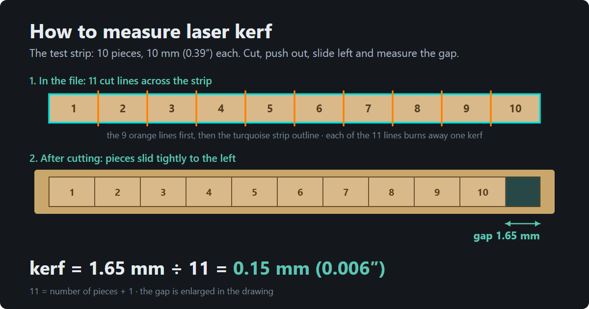
In short
- Kerf is the width of the slot the laser burns away — usually 0.1–0.3 mm (0.004–0.012 in). You measure it once for a given sheet and laser.
- Strip: cut it, push out the 10 pieces, slide them to one side of the opening and measure the gap. Example: 1.65 mm ÷ 11 = 0.15 mm (0.006 in).
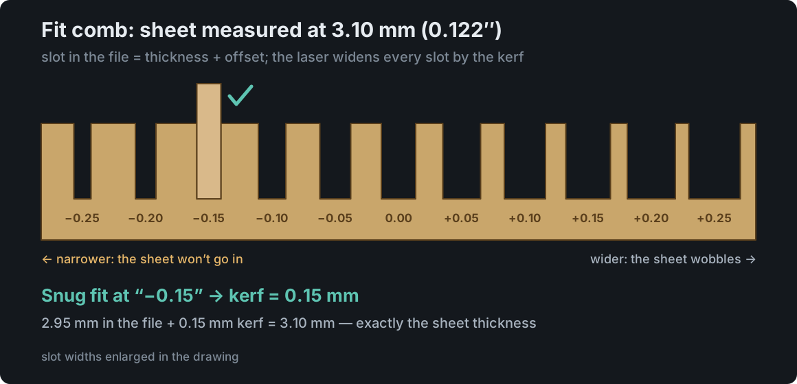
- Comb: slide an offcut of the same sheet into the slots. A snug fit at “−0.15” → kerf 0.15 mm.
- You don’t calculate anything yourself. Enter the measured thickness and kerf (or pick the material from the library) and the generators widen the fingers and narrow the notches so the joints press-fit after cutting.
What kerf is and why you should measure it
A laser doesn’t cut like a knife, right on the line. It burns away a slot as wide as its spot — that is the kerf. The centre of the beam follows the line in your file, so half a kerf disappears on each side of the line.
Example: in the file a finger is 10 mm wide and the notch for it is 10 mm too. With a 0.15 mm kerf the finger comes out at 9.85 mm and the notch at 10.15 mm. That’s 0.3 mm (about 0.012 in) of play — the box rattles and puzzle pieces fall out of the frame. For decorations it doesn’t matter; for press-fit joints it decides everything.
Laser manufacturers don’t list kerf, because it depends on the lens, focus, material, power and speed. That is why the software starts from an estimate (0.1 mm for a diode laser, 0.15 mm for CO₂) and labels it as one — only a measurement gives you the real value. It takes a few minutes.
In what order to run the tests
If you are starting from scratch — a new laser or a new sheet — go in this order:
- Focus ramp — a blurry beam gives a wider kerf and a weaker cut, so focus comes first.
- Power × speed grid in “Cutting” mode — so you know which settings cut the sheet all the way through.
- Kerf measurement with the strip or the comb — using those cut settings.
For engraving, the grid in “Filled engraving” or “Line engraving” mode is all you need.
Before you start: measure the sheet
Plywood sold as “3 mm” or “1/8 inch” is usually anywhere from 2.7 to 3.3 mm (0.106–0.130 in), and two batches from the same supplier can differ by a few tenths of a millimetre — more than the kerf itself. Measure the sheet with calipers in 2–3 places away from the edges and use the average. Example: 3.12 + 3.08 + 3.10 mm → 3.10 mm (0.122 in).
In the Material tests, enter it in the “Thickness (mm)” field under “Material”, along with the sheet name. The fit comb sizes its slots from this thickness, and the box generators use it for the finger depth.
Measuring kerf with the strip — step by step
- Open Material tests → Kerf measurement. Keep the default 10 pieces of 10 × 20 mm.
- Under “Helper layer settings”, enter the cut power and speed that cut your sheet all the way through (if you don’t know them yet, run the grid first).
- Download the file (LightBurn .lbrn2 or SVG) and cut the test. The order matters: first the orange lines between the pieces, then the turquoise strip outline, and the red plate outline last. If the strip outline went first, the whole strip would drop out before the laser split it into pieces. The .lbrn2 file already has this order; with SVG, set it in your laser software. Don’t move the sheet until the laser has finished.
- Push all 10 pieces out of the opening and put them back, sliding them tightly to one side — no gaps between them, but don’t force them. The order of the numbers doesn’t matter.
- There is now a gap on the other side. Measure it with calipers — using the inside jaws (the small ones on top) or a feeler gauge. In our example: 1.65 mm.
- Type it into “Measured gap (mm)” in the right-hand panel. The software shows: Kerf = 1.65 ÷ 11 = 0.15 mm.
- With an account, click “Save to the Material library” — the kerf is stored for this sheet and your active laser.
Why “÷ 11”?
The laser cuts across the strip 11 times: the left edge of the opening, the 9 lines between the pieces and the right edge. Each of those cuts takes away one kerf width — the opening gets slightly bigger and every piece slightly smaller. When you slide the pieces to one side, all those losses add up in a single gap: 11 × kerf. So kerf = gap ÷ 11. If you change the number of pieces to N, you divide by N + 1 — the software does that for you.
Why not just measure one piece?
Because 0.15 mm of kerf is about the thickness of a sheet of paper. Ordinary calipers are off by 0.02–0.05 mm, so on a single piece the error can be a third of the result. The gap collects 11 kerfs, so the same caliper error is divided by 11 — 0.05 mm becomes only about 0.005 mm.
Something doesn’t add up?
- The pieces won’t come out — the sheet isn’t cut through. Fix the cut settings (grid) and cut the strip again; a half-cut strip gives a wrong result.
- The gap is wider at the top than at the bottom — in thicker sheets the beam cuts a slight wedge. Measure halfway down, and if the difference is big, check the focus.
- The kerf comes out well over 0.3 mm — most often the focus is off or the power is too high for the speed. The software also warns you if the result is over 1 mm (usually a gap typed in the wrong units).
- The edges are coated in resin or soot — wipe them, but don’t sand them: sanding changes the size of the pieces.
The fit comb — kerf checked in practice
The strip gives you a measured number. The comb shows what really matters in a joint: how the sheet goes into a slot. It also helps if your calipers have no inside jaws.
- Choose Slot fit. The thickness field must hold the measured thickness, e.g. 3.10 mm — the slots are sized from it.
- Keep the 0.05 mm step and 5 slots per side. You get 11 slots: 2.85 to 3.35 mm in the file, labelled from “−0.25” to “+0.25” (the offset from the thickness).
- Cut the comb. Take a test piece from the same sheet — for example one of the strip pieces or an offcut with a straight edge.
- Slide it into the slots one by one. You are looking for the one it goes into snugly, with clear resistance but without a hammer, and that holds it when you turn the comb upside down.
- In the right-hand panel, pick its label under “Slot that fits tightly”, e.g. “−0.15”. The software shows: kerf ≈ 0.15 mm.
Why is the kerf “minus the offset”?
The “−0.15” slot is 3.10 − 0.15 = 2.95 mm wide in the file. The laser widens it by the kerf. If a 3.10 mm sheet fits it perfectly, then 2.95 mm + kerf = 3.10 mm, so the kerf is 0.15 mm.
It fits “in between”
Sometimes the sheet goes into “−0.15” only with effort, and already wobbles a little in “−0.10”. The kerf is then somewhere in between. For press-fit joints without glue, pick the tighter slot (−0.15); for glued joints the looser one (−0.10), because glue needs a little room. The rule: a bigger kerf in the software = tighter joints.
If a slot with a plus sign fits snugly, the software flags it — almost always the thickness field holds the label value instead of the measured one (e.g. 3.0 for a 3.25 mm sheet).
Strip or comb?
Ideally both. If the results differ by 0.02–0.03 mm, all is well. For joints, go with the comb result — it is exactly the same situation as in a box: a sheet in a slot.
What the software does with kerf and thickness
You measure kerf and thickness once. The software does the rest — you don’t move lines, edit the drawing or set a correction in your laser software.
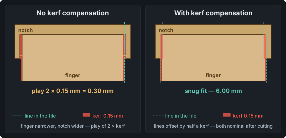
- Wider fingers, narrower notches — by half a kerf on each side. With a 0.15 mm kerf a 10 mm finger is drawn 10.15 mm wide in the file and the notch 9.85 mm. The laser removes 0.075 mm on each side of the line, and after cutting both are exactly 10.00 mm. The joint press-fits with no play.
- Finger depth = sheet thickness. That is why the measured thickness matters so much. If the sheet is 3.25 mm and you enter 3, the fingers won’t reach all the way through the neighbouring panel and the notches will be too shallow — the box may not go together. When the thickness looks like a label value (a round 3 mm), the software reminds you before you download the file.
- Slots for dividers are drawn a touch narrower than the sheet, allowing for the kerf, so the divider sits tight.
- Slip-on lids get their clearance increased by the kerf, so they come off without a fight.
- Puzzles have their outer outline offset by half a kerf, so the finished puzzle is exactly the size you set.
This applies to the box, money box, house, bird feeder and puzzle generators. They take the kerf from the Material library: pick the material and the thickness and kerf saved for your laser fill in on their own. Without a saved material you type them into “Material thickness” and “Kerf width”. More on the joints themselves in Finger joint box design.
Watch out for double correction: files from the generators already have kerf compensation built into the drawing. Don’t add a “Kerf Offset” in LightBurn on top — the joints will come out too tight. Kerf Offset is useful for your own drawings that have no compensation.
Power × speed grid — how to pick a square
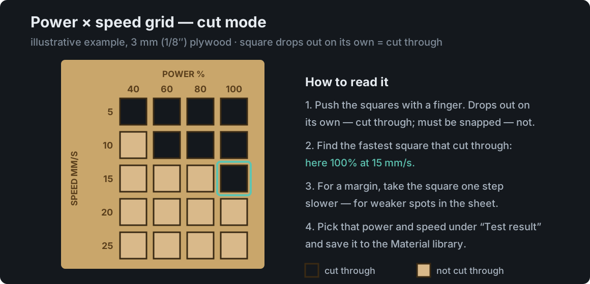
In “Cutting” mode with the default settings you get 20 squares of 8 × 8 mm: power 40, 60, 80 and 100% in the columns and speed 5, 10, 15, 20 and 25 mm/s in the rows. Each square is its own layer with its own power and speed, so you cut the whole thing in one run.
- Choose Power × speed and “Cutting” mode. If your laser is much stronger (CO₂) or weaker, shift the speed range.
- Cut the plate and push the squares with a finger. A square that drops out on its own or with a light touch is cut through. One you have to snap out is not.
- Find the fastest square that cut through — in the example 100% at 15 mm/s. If several powers cut through at that speed, take the lowest. More speed and less power mean fewer burn marks.
- For a safety margin you can take the square one step slower (100% at 10 mm/s) — it helps with weaker spots in the sheet, like a thicker glue line.
- In the right-hand panel, pick that power and speed under “Best power” and “Speed” and save it to the Material library.
For engraving, pick “Filled engraving” mode (or “Line engraving” for thin lines) and look for the square with the colour you like — even, with no scorched edges. Of two similar squares, take the faster one. Dark squares run diagonally across the grid because what counts is the ratio of power to speed: 60% at 10 mm/s delivers roughly as much energy as 30% at 5 mm/s. More on reading the grid and typical ranges for different lasers: Plywood laser cutting settings.
Focus ramp — reading the scale
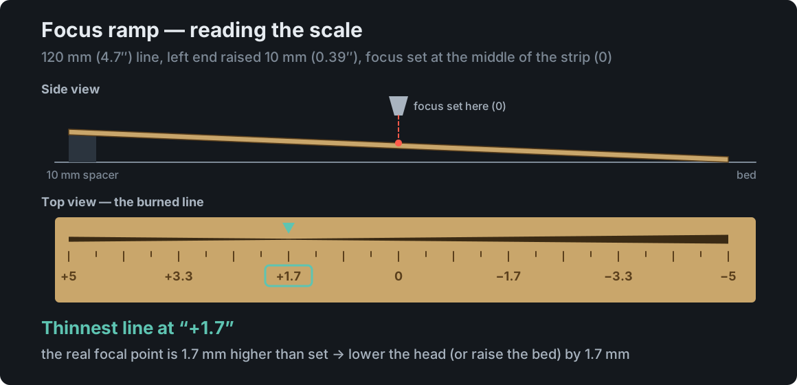
The ramp shows whether the focal point is where you think it is. The laser draws a line along a strip laid at an angle — where the surface meets the real focal point, the line is thinnest.
- Choose the Focus ramp. Keep the 120 mm line and the 10 mm rise.
- Take a strip of sheet longer than 12 cm (5 in). Rest the left end on a 10 mm (0.39 in) spacer — a block or a few layers of sheet — and the right end on the bed.
- Focus the way you always do (focus gauge or autofocus), but in the middle of the strip — that is where zero lands on the scale.
- Run the test. The laser burns the line and a scale from “+5” to “−5”.
- Look at the line up close (a magnifier or a zoomed phone photo) and find where it is thinnest and sharpest. Read the number below it — in our example +1.7.
- Type it into “Thinnest line at marker (mm)”. The software tells you what to do: at “+1.7” the real focal point is 1.7 mm higher than set — lower the head (or raise the bed) by 1.7 mm. With a minus number it is the other way round; at zero your focus is right.
When the ramp shows an offset, fix your focus gauge or autofocus setting once and for all. Lenses, gauges and focusing in thick sheets are covered in our Laser focus guide.
Save the result and never test twice
With a Laser MTS account you save each result with one click to the Material library — for this sheet and your active laser: the grid stores cut or engrave power and speed, the strip and the comb store the kerf, and the ramp adds a note. The material’s other settings stay untouched. Without an account the tests work in full; you just note the result yourself.
Repeat the test when you buy sheets from a different supplier or in a different thickness, after replacing or cleaning the lens, and on every new laser. For the bigger picture — and why charts from the internet are not enough — see Laser material test.
Frequently asked questions
What is a typical laser kerf?
Usually 0.1–0.3 mm (0.004–0.012 in). But the same laser gives a different kerf on a different sheet, at a different focus and with different cut settings. The software starts from 0.1 mm for a diode laser and 0.15 mm for CO₂, but measuring with the strip takes a few minutes and gives you the value for your own sheet.
Does kerf depend on sheet thickness?
Yes. In a thicker sheet the beam cuts a slight wedge and the cut takes longer, so the kerf usually grows. That is why you should store kerf separately for each sheet — the Material library keeps it together with the thickness for every material and laser.
Do I need to set Kerf Offset in LightBurn?
Not for files from the Laser MTS generators — kerf compensation is already in the drawing, and a second correction makes the joints too tight. Kerf Offset is useful for your own drawings without compensation.
Do I need calipers to measure kerf?
For the strip, yes — cheap digital calipers with inside jaws are enough. The fit comb works without measuring the gap, but it is still worth measuring the sheet thickness with calipers.
Are the material tests free?
Yes, with no account. An account with an active plan (the free trial counts) is only needed to save the result to the Material library that the generators use.